Fiber TAP
Purchase Fiber TAP at IPNetshop.com
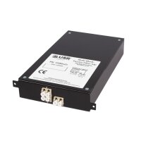
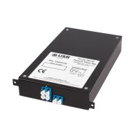
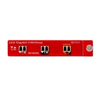
Datacom 100 Gigabit Network Fiber Tap for 2 x 40G / 100GBase LR4 Links. Taps from Datacom Systems provide your network monitoring and security tools with passive permanent access into your for 40G / 100GBase fiber network. They provide permanent in-line access to network links - eliminating the need to disconnect and reconnect network plugs every time a segment needs to be analyzed. Our Taps allow you to view Layer 1 and 2 faults that are not visible when monitoring the network with SPAN Ports.
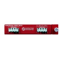
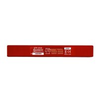
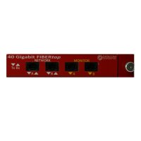
Datacom 40G series fiber network tap for connection with Cisco bidi links. Available in different variants. FTP-1518 and FTP 1718 depending on split ratio. The passive 40G Fiber Network Tap has 4 x LC style ports to connect to a 40G Cisco Bidi Fiber Link and 4 x LC bidirectional ports. This Fiber Network TAP from Datacom Systems provide your network monitoring and security tools with passive, permanent access to your 40 Gigabit fiber network. Available in two different split ratios.
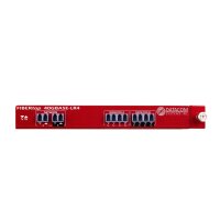
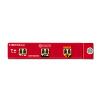
Datacom 40G-LR4 passive network fiber tap available in different variants -FTP-1516 and FTP 1716. 40 Gb passive TAP with two 40Gb LR4 network ports and 8 LC monitor ports. This fiber network TAP from Datacom Systems provide your network monitoring and security tools with passive, permanent access to your 40 Gigabit fiber network. The 40G-LR4 pairs with a 40GBase LR4 network link and sends a copy of traffic from any device on any wavelength over the LR format LC ports. With the 40G-LR4, you can access and monitor a multi-lambda fiber link by combining 4 SFP+ single wavelength ports into a native 40GbE interface on your monitoring devices. Monitor outputs are at 1271, 1291, 1311 and 1331nm.
The Datacom 40G-SR4 is a 40 Gb passive fiber network tap and available in different variants as FTP-1514 and as FTP-1714. The Fiber Network Tap has 2 MTP ports for connecting a 12 fiber strand connection and 2 MTP output ports. Datacom Systems' 40Gb fiber taps provide your network monitoring and security tools with passive, permanent access to your 40 Gigabit fiber network. Available in a number of different split ratios.
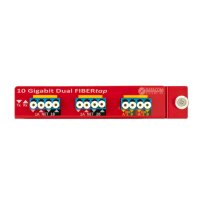
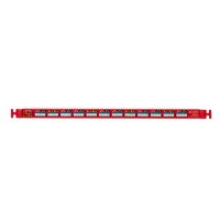
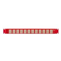
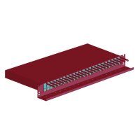
The Datacom FTP-9000 series is a High Density Network Fiber Tap with 24 x 10 GB or 1 GB (LC) full duplex fiber links. The High Density Fiber Network Tap is ideal for security, network monitoring and end-to-end performance analysis to monitor a number of links simultaneously. This passive fiber TAP provides permanent access to 24 / 10 / 1 Gigabit fiber links. Suitable for large enterprise data centers, cloud or communications service providers, or high-performance computing environments. The 9000 family is available in different variants such as split ratio, multimode and singlemode.
What is a Fiber Network Tap?
A Fiber Tap is an access point installed in networks that enables real-time monitoring of connections. Typically, the data is used to monitor security threats, performance issues, and optimize the network. A Fiber TAP is a passive device that integrates TAP functionality into a cable patching system that does not require its own power supply and does not actively interact with other components of the network. Instead of two switches or routers directly connected to each other, the optical TAP sits between the two end devices directly connected to each of them. Then the traffic is copied, and once the traffic is tapped, the copy can be used for any type of monitoring, security, or analysis. Therefore, a fiber TAP or Fiber Tap is a key component of any visibility system.
The Fiber TAP Types
There are two types of Fiber Taps - active fiber network TAPs and passive fiber network TAPs. The active network TAP requires power to operate, while the passive network TAP does not. The active network TAP is mainly used for applications that require a change in the signal sent to the monitoring port, but is only required for very specialized applications. Passive network fiber TAPs are more common in enterprises and are used for applications that require simple monitoring. The Fiber Tap as a passive network TAP is a simple and powerful way to monitor optical networks. Since no power is required and no electrical components are present, a passive fiber network TAP cannot be a source of error when used in a production network. In addition, the passive fiber network TAP is extremely reliable and requires no maintenance. Overall, a passive fiber network TAP provides access to data flowing over a network without creating a location where data can be tampered with or a potential point of failure.
How does a fiber TAP work?
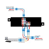
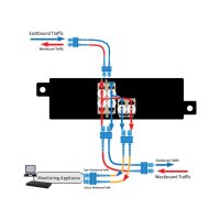
Fiber optic cables are designed to send light from a transmitter-receiver through a thin glass cable to a receiver at the other end. The two endpoints (switches, routers, databases, etc.) are not connected directly to each other, but to the network ports on the fiber network inserts. A Fiber TAP typically integrates both network and monitoring ports in one module and includes an optical splitter that "splits off" a portion of the input power and passes it to a monitoring device. Fiber network taps can be connected to Switch X and Switch Y via network ports and connect them to the monitoring device via the monitoring ports.
With the splitter, users can see that part of the TX data from Switch X is transmitted to the RX of Switch Y and another part of the TX data from Switch X is transmitted to the monitoring device. Similarly, part of Switch Y's TX data is transmitted to Switch X's RX and another part of Switch Y's TX data is transmitted to the monitor. Thus, the monitored traffic is split into two transmission signals (TX only), one copy from endpoint A (Switch X) and one copy from endpoint B (Switch Y).
Split-ratio of the fiber taps
The signal is split into two parts by the splitter. Now, what is the proportional share of the light for each path (transmission to the network and to the monitor) - the so-called optical TAP split ratio? The split ratio is given as a combination of two percentages. The first number is called the network share. The second number is the percentage for the monitor. They always add up to 100 percent. Typically, the TAP split ratio is available in 50/50 or 70/30. A 50/50 split ratio would mean that 50% of the lighting budget coming into the TAP from the network goes to the end device, and 50% of the lighting budget goes to the monitor. A 70/30 split ratio, on the other hand, would pass 70% of the lighting budget to the end device and only 30% of the lighting budget to the network monitoring device.
Fiber TAP splitting ratio
When the path to the monitoring device is short and direct, more light must be maintained on the primary links to keep both signals readable. At the limit of readability, network performance degrades due to retries and errors, even if the link does not fail completely. If the fiber network TAP does not emit enough light, the monitoring link cannot provide enough light for the monitoring device to register an accurate signal. Low light levels on the monitor link may lead to incorrect conclusions about data errors on the network link, or there may not be enough light for the appliance to register a signal at all.
